Update:
We’ve received some feedback from people who’d like to get their own replica of this and other models. That’s very cool! Have a look at the project page to get more details about this project.
References
- Project page on Meccano Kinematics website
- Solving algorithm implementation: GitHub
- Other Wilbert’s machines: YouTube channel
- More about Meccano and FAC system: Meccano Kinematics
Video
Although our FAC Solver has gathered 120K+ views on YouTube, we felt that this was only the beginning. By the time we finished it, we had a bunch of ideas in mind that we were eager to realize. While I was trying to figure out more efficient Arduino-Raspberry setup, Wilbert’s tireless genius came up with another 3-gripper machine, this time assembled with old-school (yet well-known) Meccano construction set.
While FAC Solver was more of an experimental creation, this time we had lots of experience, so we could address fundamental weaknesses of the FAC Solver, at the same time focusing on the look and feel of the machine, making it more friendly and appealing. We didn’t want to make yet another hacky DIY machine, but something that would combine technology with design, something nice to build, to see, and to own.
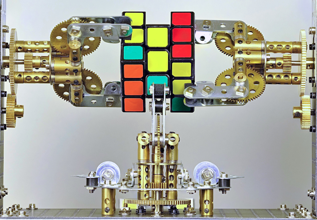
Mechanical Design: Less Wiring, More Art
Having several decades of Meccano experience, Wilbert managed to design the machine that is much more compact than the FAC solver. To achieve the cleanest look possible, all the wiring and unnecessary details are hidden inside the metal body. If necessary, the PCB board and other electronics are easily accessible through the door on the back side. Moreover, the whole machine is assembled using normal Meccano parts that are available on the internet.
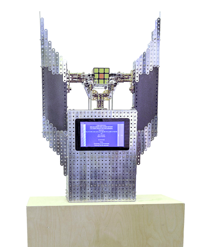
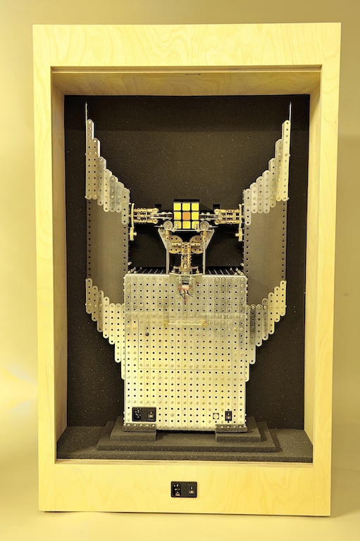 The Rubik’s Shrine in transport box
Wilbert was inspired by the Dark Tower from the Lord of The Rings, so the look of the Shrine is meant to be quite pompous :)
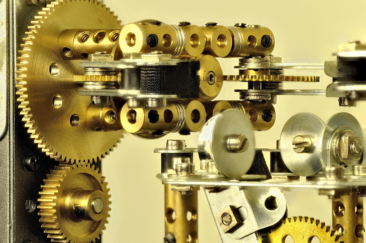
Being very careful about the details, Wilbert made sure all parts matched each other: all original rounded shiny Meccano strips, with 3-layered custom airbrush finish on the plates. Brass gears put the final touch to the appearance of the machine. The fine-grained assembly was also very important: the distance between some parts was just a couple of millimeters.
Wilbert tells more about the mechanical part on his website.
Internals: What can we do better?
We were very satisfied with our previous project, the FAC Solver, but we also knew we could do better. We learned a lot about hardware parts like stepper motors and drivers, microcontroller boards, and faced all kinds of unexpected issues on the way. This experience helped us a lot when we were building this Meccano Rubik’s Shrine.
Microcontrollers: Use the right tool for the job
In our previous project, the FAC Solver, (almost) everything was controlled by Raspberry Pi, including solving algorithm, color recognition, movement scheduling, and pulse generation for the stepper motors. We used Arduino only for reading the analog signal from LDRs in scanner device.
While it did work quite well eventually, it turned out to be tricky when it comes to controlling the motors. On the lower level, you can’t precisely control the time that processor gives to your process on RPi. Due to the presence of other processes, and, actually, the operating system itself, your program might be given different chunks of CPU time, which makes the generated pulse train unstable. For lower speeds, it is not a problem, but if the motor speed is high enough, it can be killing for performance: motors start hesitating. To overcome this problem, we decided to use an Arduino board for the actual motor control.
We’ve come a long way with the PCB board. The first fersion looked something like this (using Arduino Uno):
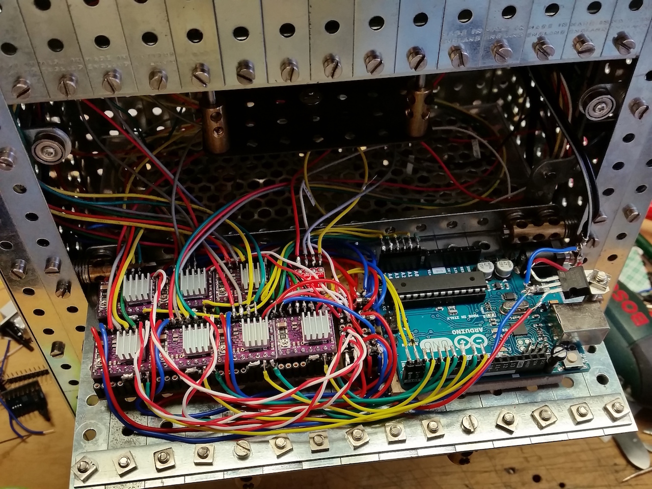 The first version of PCB board
We chose Arduino Pro Mini because it is probably the most compact one. We made the first working prototype with it, and later replaced it with the Teensy 3.2, which looks and feels almost identical, but has better performance. We also used DRV8825 for driving the stepper motors. So eventually, the PCB became this (the red thing on the left is a voltage level trigger needed for the LEDs):
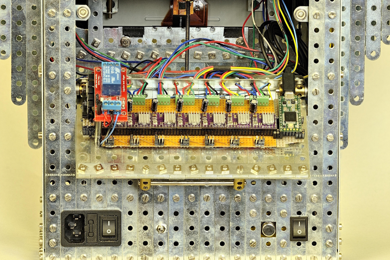 PCB board behind the door on the back side
Arduino gave us much more stable pulse train, which allowed to reach higher speeds. We also used the great AccelStepper library that made movements smoother and more reliable. As before, I used the MIN protocol for RPi-Arduino communication.
Firmware: Optimize everything!
Since software part was my main responsibility in this project, the firmware was the very first thing I cared about. Pure RPi/Python implementation of FAC Solver proved to have a number of nasty caveats, so I wanted to do it right this time. I braced myself and prepared for the challenge of embedded systems programming, ready to implement things from scratch for saving a few bytes of RAM.
Movements
Probably the most difficult part was the movement optimization. The solving algorithm produces a solution sequence on Raspberry Pi, which then needs to be translated into a sequence of gripper movements. Then this data has to be transferred to the Arduino board because actual electrical pulses are generated there. I wanted to make the algorithm generic so that I could use it in other machine configurations (with 4 or even 6 grippers). This added to the complexity of the problem.
Minimizing the overall solving time is not obvious. For example, in a 3-gripper setup like this, to rotate the Front side of the cube we need to rotate the whole cube first. We can rotate it around the vertical or horizontal axis. Whichever is better (leads to faster solution) depends on the current state of the grippers and on subsequent moves.
Synchronization
Generally, all grippers can move simultaneously. To do this, we need to have multiple parallel execution flows. Since Arduino is single-threaded, it has to be done with coroutine-like mechanism. On the other hand, due to the mechanical construction, some movements require the other grippers to be in specific positions, which means that parallel workers need to be able to block each other. Average solving process requires about 200 blocking operations.
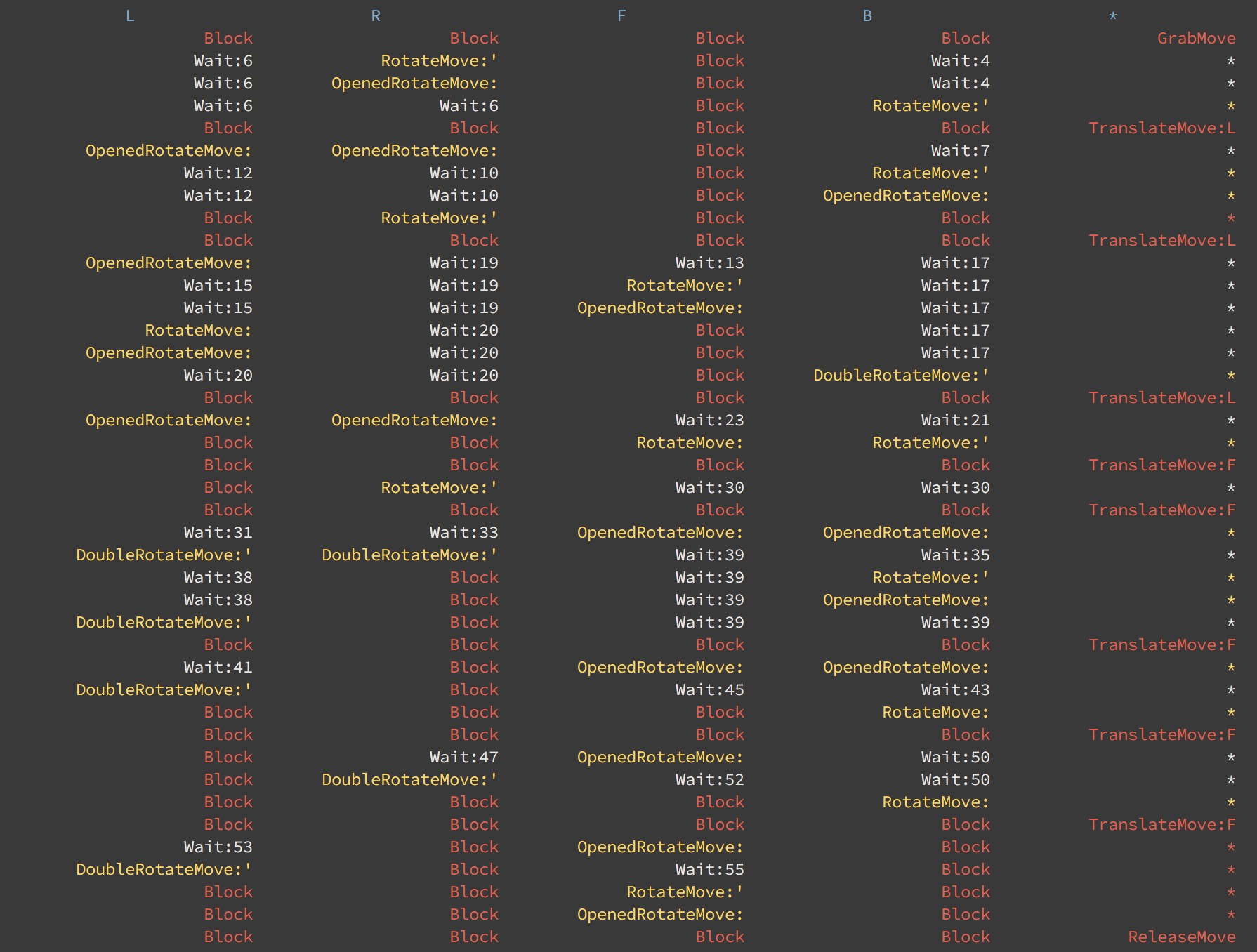 Movement scheduling for 4-gripper setup
Memory management
Arduino Pro Mini, which we used initially, has only 2KB of RAM. After initializing objects for serial communication and motor control, there are approximately 200 bytes (!) left for local variables in actual business logic. With such limited resources, I could afford to store only absolutely vital data. Everything else had to be buffered in Raspberry Pi and pushed to Arduino via serial connection during the run. Pure serial communication is quite expensive, so it was causing an additional slowdown of the solving process.
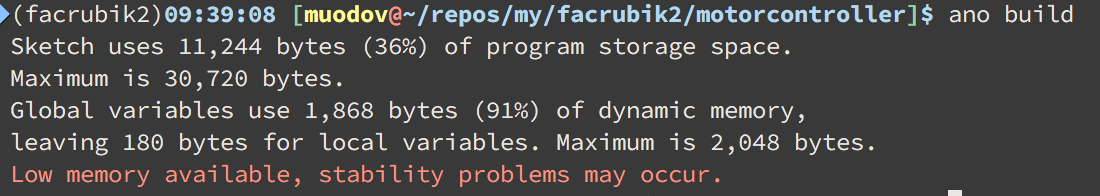 Arduino Pro Mini compilation result
It is (kinda) possible to write C++ code for Arduino, but the dialect is very limited: for the sake of memory it doesn’t have the C++ standard library, exceptions, etc., and in most cases it is a bad idea to use things like dynamic allocation. For spoiled developers like me, it is really tough to refrain from using abstract classes with a bunch of virtual methods and dynamically allocated arrays. It is really hard (I mean freaking hard) to debug because you never see the exceptions: it never fails explicitly, it just starts working weird at some point, and you can only guess what went wrong, especially if you have memory-related problems. I ended up with quite hacky virtual method implementation based on switch statements and static variables, which was lame, but straightforward.
Later, we changed the Arduino Pro Mini with Teensy 3.2 which was a great improvement. Not only it is way faster (thanks to ARM processor), and has 64KB of RAM, but it has exactly the same form-factor as Arduino Pro Mini. We didn’t even need to change the PCB connectors!
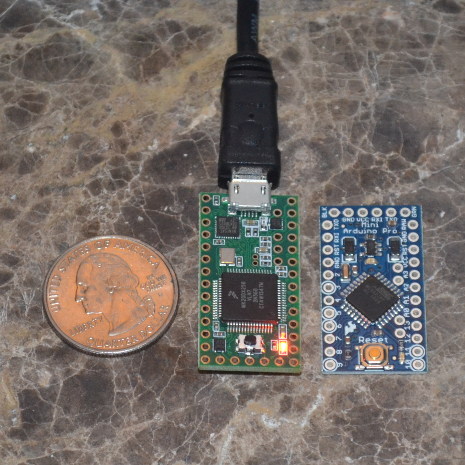 Arduino Pro Mini vs Teensy 3
Well, 64K ought to be enough for anybody, at least in Arduino world :) With all this memory available, I could easily store information about the whole movement sequence at once. No additional serial communication + increased speed = faster and smoother solving.
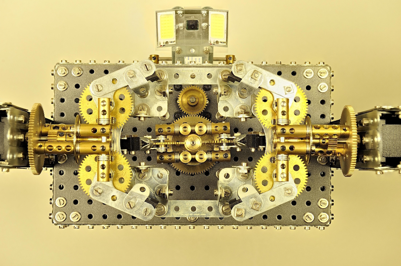
Camera: Come on, it’s the 21st century!
Apart from the motor controlling, the biggest technical change in Rubik’s Shrine, compared to the FAC Solver, was the scanning part. While it was fun to play with the low-end scanner made from LDRs and LEDs, it was quite a challenge to deal with ambient light and do the color balancing. It did fit well the brutal nature of the machine but obviously was not the most modern approach.
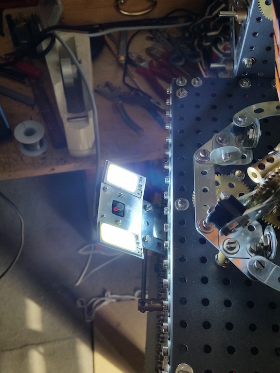 Camera with flashlight on
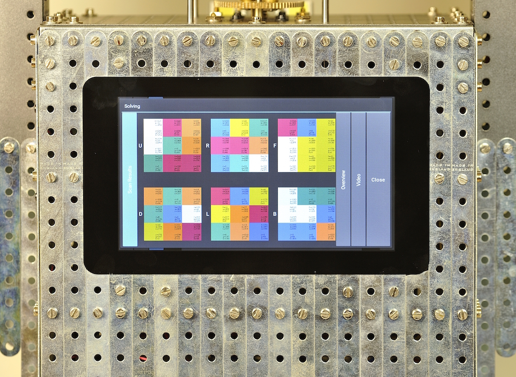
This time, we went fancy and used the Raspberry Pi Camera for color scanning the cube. Since it automatically adapts to the lighting conditions, it solved pretty much all of those color recognition problems (we had to use bright LED flashlight though). All I needed to do was to carefully pick the average colors from specific regions on the photos.
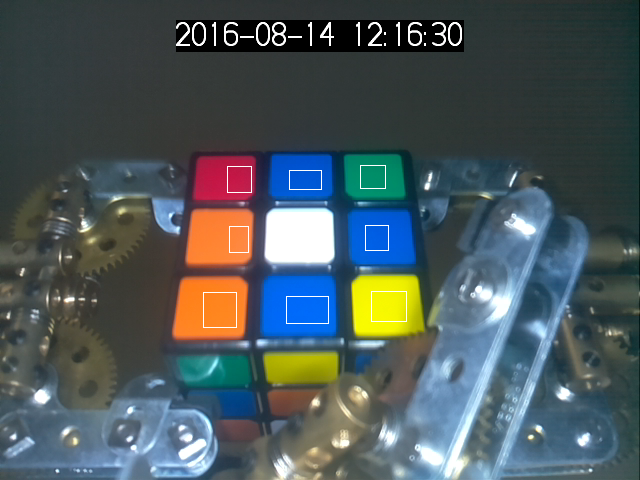 The photo of the cube with marked regions for color recognition
As a bonus, each run is recorded on video and available on the Archive page in the touch interface. It was also quite handy during debugging.
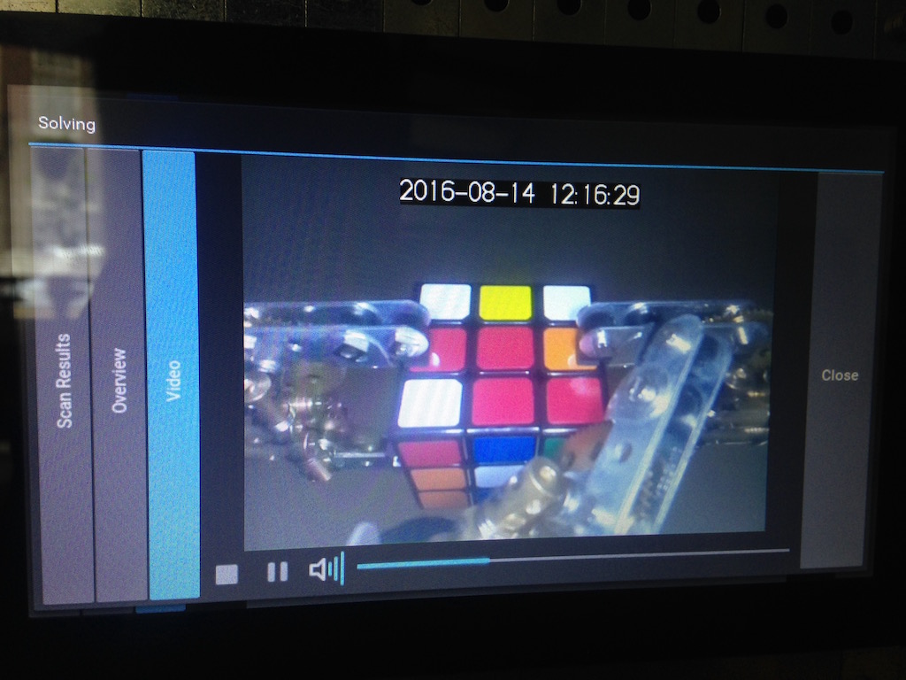 Every run is captured on video
Pi Display: the Final Touch
I just couldn’t resist. Not so long before we started this project, Pi Foundation announced an awesome 7-inch touch screen for Raspberry Pi that perfectly fitted our model. I was pleasantly surprised that it just worked: after a couple of nights I had a nice-looking touch UI written in Kivy.
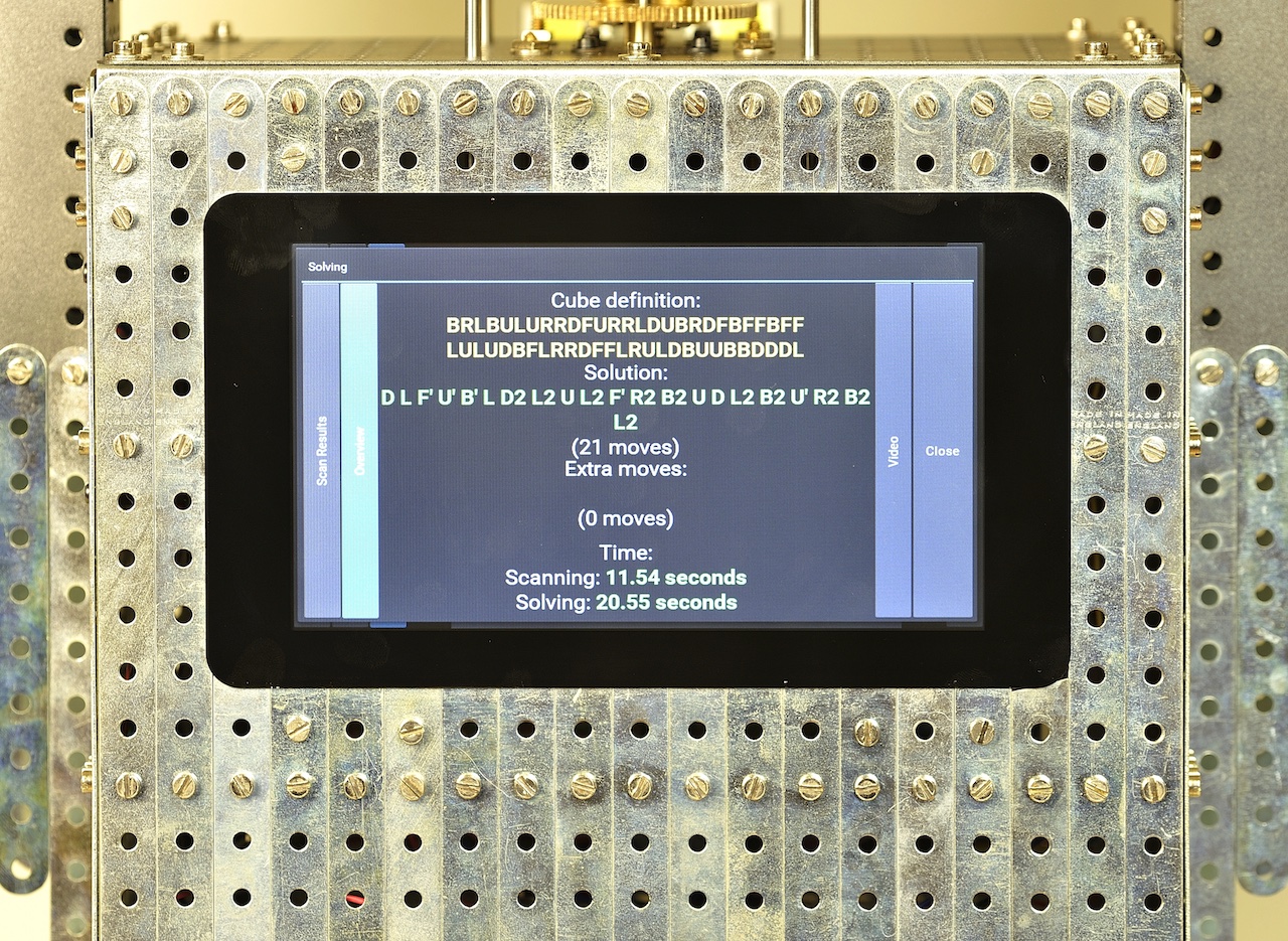
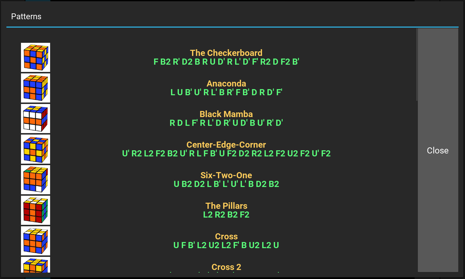
Having a touch screen, I was able to add some extra functionality to the machine. In addition to a nice presentation of the scanning and solving results, it is possible to make some pretty patterns.
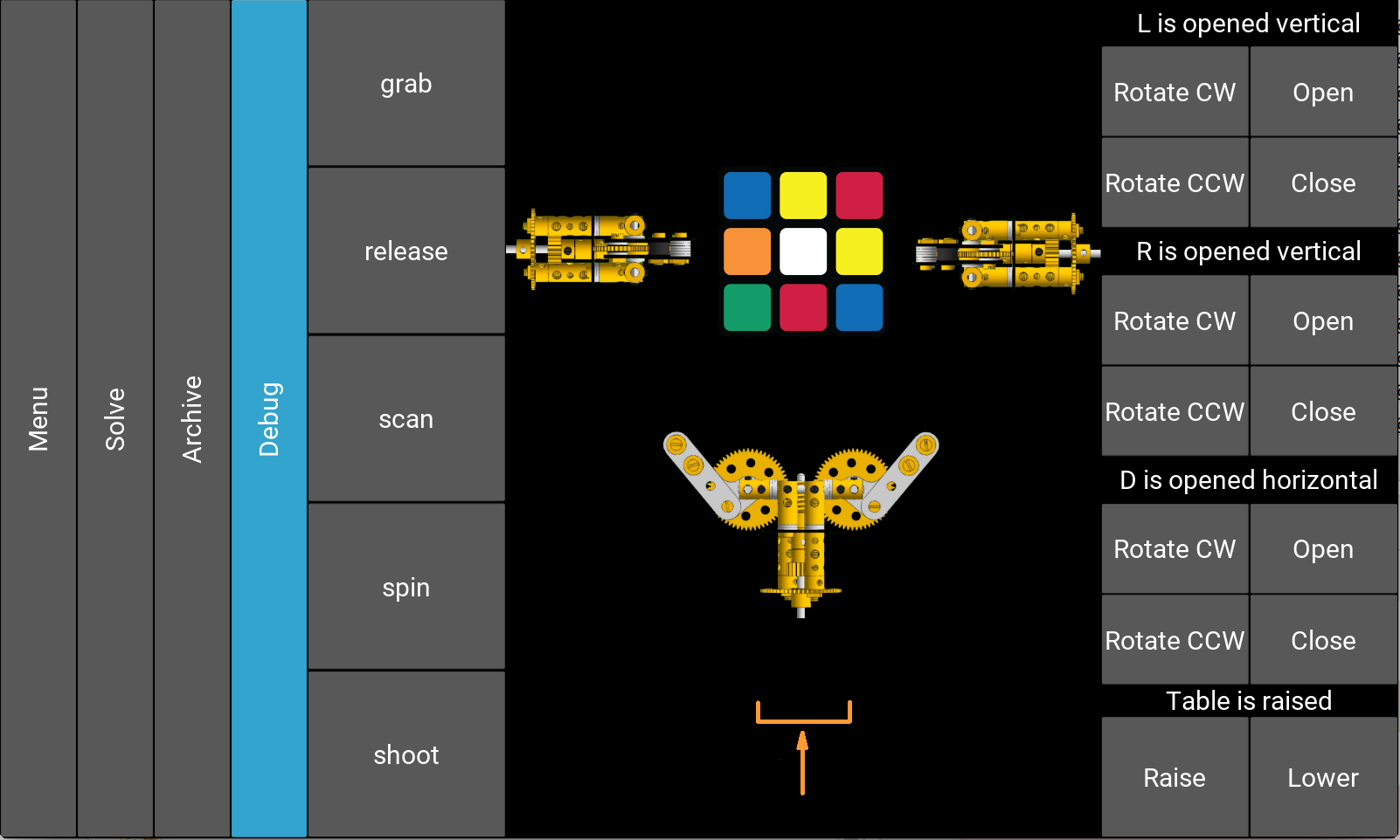
I also made a special debug screen for manual control that practically made it unnecessary to use a laptop for testing.
Public demonstrations and final words
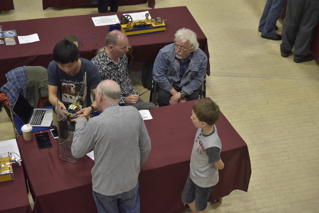
When the Rubik’s Shrine was almost finished, we presented it on SkegEx 2016, the annual Meccano exhibition in Skegness, England. We even managed to win the 5th prize, which is quite something considering that SkegEx is generally more about traditional mechanics rather than robotics and electronics.
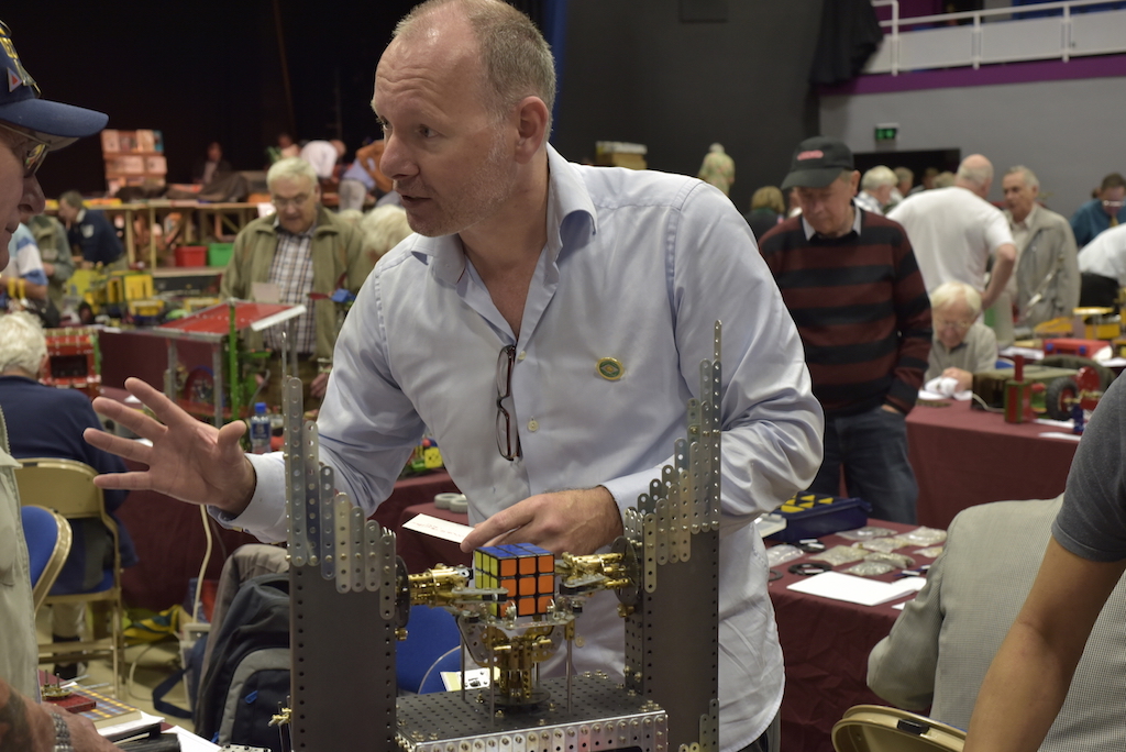
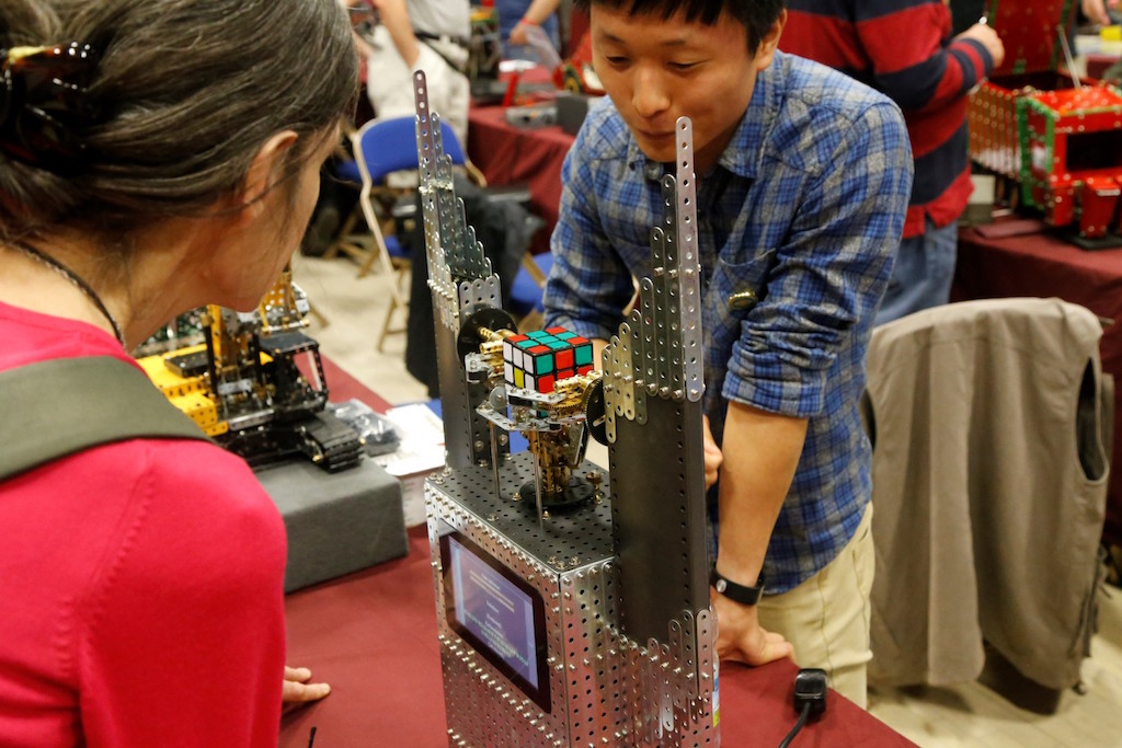
But the biggest prize for us were the gleaming eyes of kids visiting the exposition. It was wonderful to see them pulling their parents to our table over and over, just to scramble the cube and start the machine once again.
All in all, we are very satisfied with the result. Apart from all the hands-on experience, for me, as a software developer, it was very fun to work on something physical, something that I could see and touch. And I like to think that, thanks to Wilbert, we could push engineering a little bit towards art. Because this is what it is all about.